Fatigue testing is a well-established process, but accurate results depend on strict attention to detail.
Random selection of materials, test bar unit cells, and cutting methodology could skew results and put your application at risk of failure. In this second of our two-part fatigue testing series we explore how these key aspects of fatigue testing influence outcomes — and why it’s important to partner with an experienced supplier to leverage advanced testing and engineering plastics.
S-N Curve Stress Testing
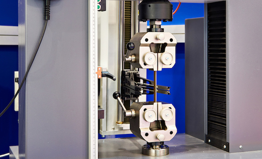
Often, fatigue testing involves stressing a dog bone-shaped test bar for a number of cycles, until the test bar breaks. To cover a range of stresses below breaking stress, four levels of testing are administered at 30%, 50%, 70%, and 90%.
The challenge lies in the assumption that the mechanical properties of the tested material are isotropic, meaning the same in all directions. In the case of glass filled engineering plastics, the mechanical properties are anisotropic and stronger in the direction of fiber orientation. Further, fiber orientation is affected by the forming process so there is no universal anisotropism.
Ideally, there is a unit cell where the microstructure of the plastic is shown to have all fibers oriented in the same direction – indicating that that area of fiber orientation is repeatable for testing purposes. Engineers must seek out and test this unit cell in order to accurately model fatigue behavior — a deceptively simple exercise.
To test properties at the point of the unit cell, rectangular plaques are injection molded and dog bone-shaped test bars are cut from the unit cell location. Fatigue bars are cut in three directions: 0 degrees in the direction of flow, 90 degrees perpendicular to flow, and 30 degrees offset from the flow direction.
Testing sample location largely drives stress testing results, which only underscores the importance of test bar location.
The Importance of Test Bar Location
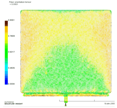
Moldflow simulations and prior testing confirm the maximum fiber orientation of glass filled engineering plastics is located in the center gate direction, about two-thirds down the flow length:
 Knowing this gives engineers a target, and it also contributes to other critical aspects of fatigue testing:
- Conservation of materials and time: Avoiding the edges will allow for the cutting of multiple test bars from one plaque, saving testing materials and time
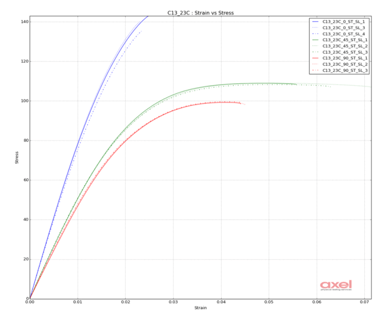
- Assurance of testing repeatability: Proving the selected unit cell is in the right location and can be tested multiple times requires 3 orientations of stress testing (0 degrees, 30 degrees, and 90 degrees):
A comparison of cut bar measurements across 3 or 4 plaques reveals if the mold and molding process yields a repeatable unit cell. If so, all of the 0-degree orientations will overlay each other without noticeable separation. Similarly, the 30 and 90-degree orientations will be well-spaced apart from the 0-degree, with no overlap to the other orientations
- Verification of tensile strength: Fiber orientation also affects tensile strength. If the plots from repeatability testing are similar to those illustrated on the chart, molded plaques are appropriate for fatigue testing:
 A recurring requirement within preparing and verifying anisotropic materials for fatigue testing is the cutting of the materials themselves (i.e., plaques and test bars). There is nothing out of the ordinary about cutting materials, but engineering plastics can present unique challenges.
A nylon with 50% glass fiber, for example, will have a flexural modulus well over 16,000 MPa. Add to it high stiffness, exposed glass fibers, and moisture absorption considerations and material cutting goes from common to complicated.
Cutting Engineering Plastics
Nylon testing is typically performed dry as molded. As such, several cutting options are available, each with its benefits and drawbacks:
- Compression die stamping: A sharp-edged metal die in the shape of the test bar is hydraulically compressed into the test plaque, making this method fast, accurate, and low-cost. However, the inability to penetrate glass, potential for shattering parts, and need for continual die sharpening are detractors. Further, this cutting method produces rough edges that, when combined with imperfections caused by fiber pull-out and stress risers, can cause premature fatigue testing failure.
- Bandsaw: As the name suggests, a bandsaw is used to follow a trace pattern of the test bar. Easy accessibility, prevalent general knowledge of bandsaw operation, and low cost make this option attractive. However, precision cutting is skill-dependent, often slow, and can leave rough edges that could lead to fatigue testing failure if other conditions are present (see above).
- Water jet: A computer-guided water jet cuts test bar patterns through stacks of multiple plaques, resulting in cutting time efficiency and smooth edges. The downside is that a water jet is arbitrary in the amount of material it removes while moving, making for inconsistent final length and width dimensions. Also, since most labs aren’t equipped with a water jet, cutting is typically done at a higher cost and takes a longer time because of the outsourcing involved. The biggest detractor to water jet cutting is placing highly absorbent nylon into a moisture-rich environment. The combination leads to nylon plasticization and higher ductility that may erroneously extend the fatigue life in testing.
- Computer Numerical Control (CNC) machine: A router created for milling, drilling and cutting materials, a CNC machine accurately and quickly traces the same pattern using a 2- or 4-flute cutting tool that resembles a drill bit. Generally, better results and relatively smooth edges are obtained using higher speeds and a 2-flute cutting tool when cutting test bars.
This broad overview of key aspects of fatigue testing reveals how dynamic the process is, and how results inform selection of engineering plastics for applications. It also demonstrates the need to partner with a supplier experienced in materials characteristics, behaviors, and fatigue testing optimization to align plastics with your application.
Reach out to the Teknor Apex team to learn more about fatigue testing, our wide range of engineering plastics, and our expert guidance in combining the two for successful outcomes.